

Mod Details
PremiumNo Difficulty Mod ID1342
Creditevilution
For
Mod ID1342
Creditevilution
For
 Linkhttps://evilution.co.uk/mod/453-touchscreen-pinout.htm Copy to Clipboard
Smart Media Stereo Connections Overview
The touchscreen unit is designated A40/3 by smart.
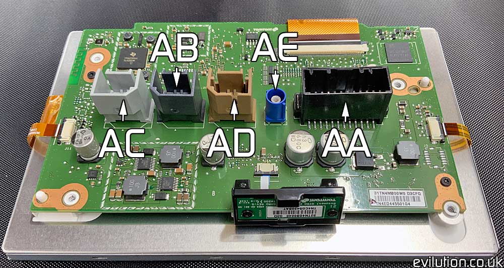
Connector AA

| Pin Number | Wire Colour | Function |
| 1 | Grey/White | CAN Bus High |
| 2 | Brown/White | CAN Bus Low |
| 3 | Yellow | Microphone + |
| 4 | Red | Microphone Signal |
| 5 | Pink/White | Navigation On/Off |
| 6 | Red | Power |
| 7 | Black | Ground |
| 8 | Red | Screen Audio Left + |
| 9 | Yellow | Screen Audio Right + |
| 10 | Brown | Screen Audio – |
| 11 | Black | Screen Audio Shielding |
| 12 | Green/White | Speed Signal Pulse |
| 13 | Yellow | Navigation Voice + |
| 14 | Red | Navigation Voice – |
| 15 | Black | Navigation Voice Shielding |
| 16 | Black | Microphone Shielding |
| 17 | ||
| 18 | Red/White | Reverse Camera Video Signal |
| 19 | Yellow/White | Reverse Camera – |
| 20 | Brown/White | Reverse Camera + |
| 21 | Grey | Reverse Camera Shielding |
| 22 | ||
| 23 | ||
| 24 |

Connector AB
USB and SD card card reader unit
Connector AC
Connects to the radio unit
Connector AD
Telematics Unit
Connector AE
Blue FAKRA C GPS Antenna Connector
Connector AB, AC & AD Further Information
Interestingly, despite the bespoke look of these connectors, they are just USB mini B leads with keyed housings. You can get almost any USB mini B lead and use a knife to trim the lead housing rubber to suit.
453 Radio Unit
The R-Link touch screen connects to a box that does all of the work like radio modulation. It’s screwed behind the dashboard just behind the touchscreen. The pin out connections for this unit can be found here.
What Is A Telematics Unit?
You do know that Google searches exist right? You could just search it.
Credits
Thanks to Askold from GoSmart for the corrections