

Mod Details
PremiumNo Difficulty Mod ID1858
Creditevilution
For
Mod ID1858
Creditevilution
For Linkhttps://www.evilution.co.uk/mod/451-mhd-starternator-wiring.htm Copy to Clipboard
Starter Alternator Unit
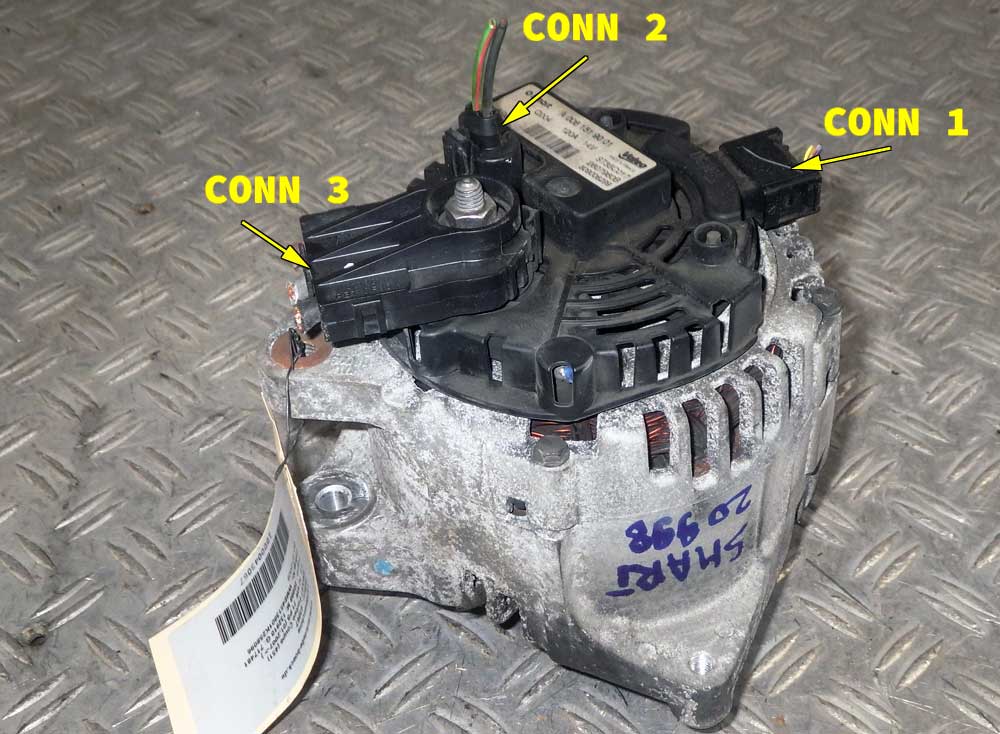
Connector 1
| Pin Number | Wire Colour | Connects To | Function |
| 1 | Brown/Yellow | Starter Alternator Controller Pin D2 | Ground |
| 2 | Violet/White | Starter Alternator Controller Pin K3 | Sensor 5 volts |
| 3 | Orange/Violet | Starter Alternator Controller Pin E4 | Sensor V |
| 4 | Yellow/Green | Starter Alternator Controller Pin D4 | Sensor U |
| 5 | Blue/Pink | Starter Alternator Controller Pin F4 | Sensor W |
| 6 | No Connection | No Connection | No Connection |
The 3 sensors measure the rotation speed because the unit is essentially a 3 phase motor, so the motor tells the controller the position of the rotor so it can switch the phases to either spin it as a starter motor or accept 3 phase power as an alternator.
Connector 2
| Pin Number | Wire Colour | Connects To | Function |
| 1 | Black/Blue | Starter Alternator Controller Pin L4 & M4 | Generator Exciter – |
| 2 | Green/Red | Starter Alternator Controller Pin L3 & M3 | Generator Exciter + |
The exciter system is responsible for supplying the field current to the main rotor. Without the exciter, it wouldn’t be able to build up or regulate the voltage created.
Connector 3
| Pin Number | Wire Colour | Connects To | Function |
| 1 | Brown | Starter Alternator Controller 3 Phase Connector | Phase 1 |
| 2 | Grey | Starter Alternator Controller 3 Phase Connector | Phase 2 |
| 3 | Black | Starter Alternator Controller 3 Phase Connector | Phase 3 |
3 Phase Controller
This unit turns DC into 3 phase AC to turn the motor as a starter motor. It also converts 3 phase AC back to DC to charge the battery.
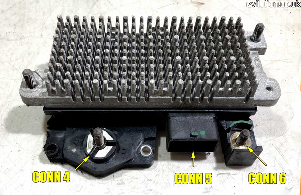
Connector 4
| Pin Number | Wire Colour | Connects To | Function |
| 1 | Brown | Starter Alternator Connector 3 | Phase 1 |
| 2 | Grey | Starter Alternator Connector 3 | Phase 2 |
| 3 | Black | Starter Alternator Connector 3 | Phase 3 |
Connector 5 is a bit bizarre the way it’s labelled. It has 3 rows numbered 2 (top), 3 (middle) and 4 (bottom). However, the pins are lettered instead of numbered.
L & M are probably the larger pins to the right since the have thicker wires connected. I would imagine they are labelled A, B, C, D, E, F, G, H, J, K, L, M.
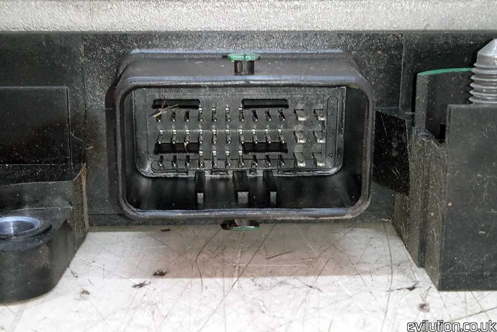
Connector 5
| Pin Letter | Wire Colour | Connects To | Function |
| A2 | Green | Speedo Pin 9 | CAN Bus Low |
| B2 | Green | ESP Controller Pin 14 | CAN Bus Low |
| D2 | Brown/Yellow | Starter Connector 1, Pin 1 | Ground |
| J2 | Black/Yellow | SAM Unit Fuse 10 | Switched Live |
| M2 | Red/White | SAM Unit Fuse 12 | Permanent Live |
| A3 | Grey/Pink | Start/Stop Button Pin 1 | Stop/Start On |
| E3 | Grey/Violet | Brake Pressure Switch | Brake Pressure Switch |
| J3 | Pink/Brown | Transmission Controller Pin 22 | Sperre |
| K3 | Violet/White | Starter Connector 1, Pin 2 | Sensor 5 Volts |
| L3 | Green/Red | Starter Connector 2, Pin 2 | Motor Exciter + |
| M3 | Green/Red | Starter Connector 2, Pin 2 | Motor Exciter + |
| A4 | Green/White | Speedo Pin 6 | CAN Bus High |
| B4 | Green/White | ESP Controller Pin 35 | CAN Bus High |
| C4 | Orange/Blue | Start/Stop Button Pin 2 | Stop/Start Off |
| D4 | Orange/Violet | Starter Connector 1, Pin 4 | Rotation Sensor U |
| E4 | Blue/Pink | Starter Connector 1, Pin 3 | Rotation Sensor V |
| F4 | Yellow/Green | Starter Connector 1, Pin 5 | Rotation Sensor W |
| G4 | Blue/White | Battery Sensor | LIN Bus |
| L4 | Black/Blue | Starter Connector 2, Pin 1 | Motor Exciter – |
| M4 | Black/Blue | Starter Connector 2, Pin 1 | Motor Exciter – |
Connector 6
| Pin Number | Wire Colour | Connects To | Function |
| 1 | Red | 12V Battery + | 12 Volts |