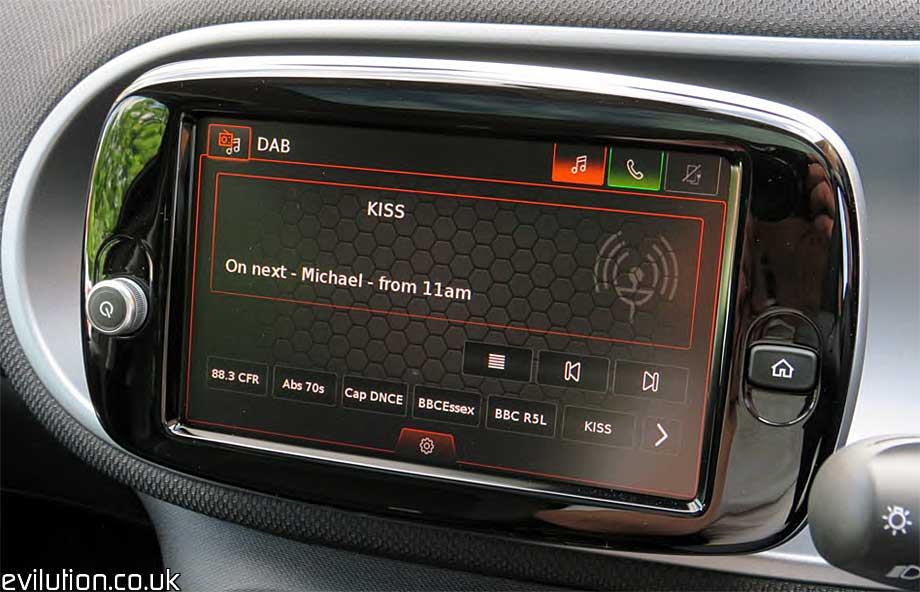
Bosch “Smart Media-System Connect”
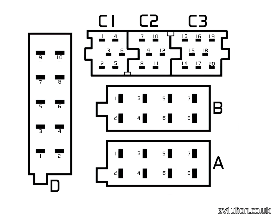
Connector A
| Pin Number |
Wire Colour |
Function |
|
|
|
| 1 |
|
|
| 2 |
Grey/White |
CAN Bus High |
| 3 |
Brown/White |
CAN Bus Low |
| 4 |
Pink |
On/Off Signal Audio Gateway Controller Pin 11 (Amplifier pin 11, if present) |
| 5 |
|
|
| 6 |
|
|
| 7 |
Red/Brown |
Fuse 26 |
| 8 |
Black/Brown |
Ground/Earth |
Connector B
| Pin Number |
Wire Colour |
Function |
|
|
|
| 1 |
Green |
Right Rear Speaker + |
| 2 |
White |
Right Rear Speaker – |
| 3 |
Violet |
Right Front Speaker + |
| 4 |
Green |
Right Front Speaker – |
| 5 |
Pink |
Left Front Speaker + |
| 6 |
Green |
Left Front Speaker – |
| 7 |
White |
Left Rear Speaker + |
| 8 |
Grey |
Left Rear Speaker – |
Connector C1
| Pin Number |
Wire Colour |
Function |
|
|
|
| 1 |
|
|
| 2 |
|
|
| 3 |
|
|
| 4 |
|
|
| 5 |
|
|
| 6 |
|
|
Connector C2
| Pin Number |
Wire Colour |
Function |
|
|
|
| 7 |
|
|
| 8 |
|
|
| 9 |
|
|
| 10 |
|
|
| 11 |
Green/White |
On/Off Signal, Audio Gateway Controller Pin 1 |
| 12 |
Black/White |
Ground/Earth |
Connector C3
| Pin Number |
Wire Colour |
Function |
|
|
|
| 13 |
Yellow |
Reversing Camera |
| 14 |
|
|
| 15 |
Black |
Reversing Camera |
| 16 |
Red |
Reversing Camera |
| 17 |
|
|
| 18 |
Brown |
Reversing Camera |
| 19 |
Black |
Earth/Ground |
| 20 |
|
|
Connector D
| Pin Number |
Wire Colour |
Function |
|
|
|
| 1 |
Red |
USB Panel |
| 2 |
Yellow |
USB Panel |
| 3 |
Black |
USB Panel |
| 4 |
Brown |
USB Panel |
| 5 |
NC |
|
| 6 |
Black |
Shielding |
| 7 |
Red |
Microphone |
| 8 |
Brown |
Microphone |
| 9 |
Yellow |
Microphone |
| 10 |
Black |
Microphone |
It’s A Bit Vague In Places
These are the colours and positions from my own car. When I compare the colours and positions against the smart wiring diagram, they don’t match but they are close. So I have given vague connections so you know what they go to in general but not specific functions for each wire.


 Mod ID1795
Creditevilution
For
 Linkhttps://www.evilution.co.uk/mod/453-bosch-stereo-pin-out.htm Copy to Clipboard